
What is a GRIN Lens?
A “GRIN lens” is an abbreviated term referring to a GRaded INdex lens, which is a cylindrical glass object exhibiting a parabolic decrease in refractive index from the central axis to the peripheries. The end surfaces of a GRIN lens are both flat. GRIN lenses are used for various applications such as collimated light beam generation, laser diode beam shapers, endoscopes and optical scanners.
The principle behind GRIN lenses has a long history that dates back their invention, by Junichi Nishizawa and Ichiemon Sasaki, in 1964. The graded index type multimode optical fibers have been employed in high-speed optical communications in the 1980s-1990s.
GRIN lenses that are fabricated by Li and Ag ion diffusion in multicomponent glasses can achieve the desired refractive index distribution. Additionally, lenses comprising vitreous silica doped with Ge or Ti can also achieve the graded index.
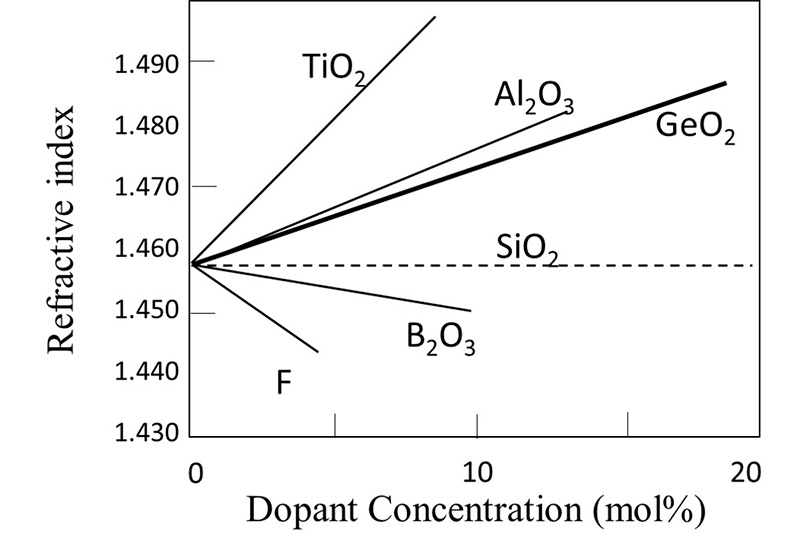
Figure 3-1 shows the refractive index change of silica glasses doped with Ge, Ti, Al, B and F elements as a function of the dopant concentration.
Figure 3-1 shows the refractive index change of silica glasses doped with Ge, Ti, Al, B and F elements as a function of the dopant concentration.
The horizontal axis shows element concentration (mol.%) and the vertical axis presents the refractive index of silica glass. The refractive index increases as a function of dopant concentration for Ge, Ti and Al, while B and F result in a decrease of the refractive index. Ge is generally incorporated into silica glasses for GRIN lenses. Even though Ti-doped silica glasses demonstrate the greatest influence in changes to the refractive index, light absorption is likely to occur, and with Al-doped quartz glasses inducing crystallization, so Ge is preferred.The horizontal axis shows element concentration (mol.%) and the vertical axis presents the refractive index of silica glass. The refractive index increases as a function of dopant concentration for Ge, Ti and Al, while B and F result in a decrease of the refractive index. Ge is generally incorporated into silica glasses for GRIN lenses. Even though Ti-doped silica glasses demonstrate the greatest influence in changes to the refractive index, light absorption is likely to occur, and with Al-doped quartz glasses inducing crystallization, so Ge is preferred.
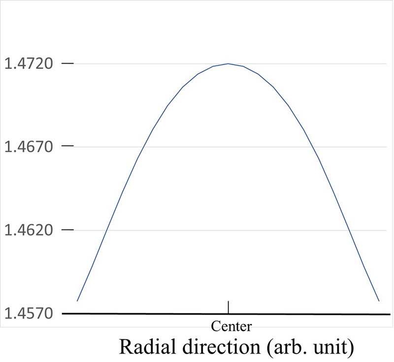
Figure 3-2 shows the refractive index distribution of a GRIN lens in which the center of the cylindrical silica glass contains a larger amount of Ge, with the Ge concentration gradually decreasing toward the peripheries. The refractive index directly relates to the Ge concentration; thus, the refractive index becomes a square distribution profile as a function of distance in the radial direction, which provides a lens effect.
Now, assuming that the refractive index at a position removed from the optical axis (the center of the GRIN lens) by r in the radial direction is n (r), and the refractive index at the lens center is n (0), then n (r) is approximately expressed by equation (1):
n(r)2=n(0)2[1-(gr)2 + h4(gr)4 + h6(gr)6 +・・・・・] (1)
Here, g is a second-order coefficient (unit: mm−1), referred to as the g value, that determines the focal length. h4 and h6 are higher-order coefficients related to aberration. In the case of a light beam propagating near the optical axis (center of the lens), there is a practical need to consider the second-order terms. In this case, the g value is given by equation (2):
g=(1/r)*[1- (n(r)2/n(0)2]1/2 (2)
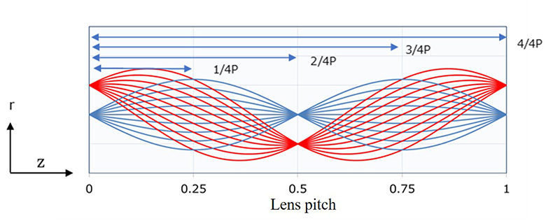
Light propagating in the z direction in the GRIN lens is represented by a trigonometric function that includes the g value. Figure 3-3 shows the ray trace in the GRIN lens. Light travels periodically while meandering through the GRIN lens. If the period is P, then P = 2π/g. The light incident, as a point light source at the center of the lens, becomes a collimated beam at 1/4P and 3/4P and focuses at 2/4P (inverted) and 4/4P (erect).
3-2.What is an integrated GRIN lens? (i-GRIN®)
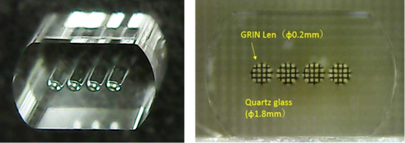
Nakahara Opto-Electronics Labs., Inc. has developed an integrated GRIN lens (i-GRIN®), a new type of GRIN lenses, composed of an array of Ge-doped silica glass GRIN lenses with the outer section covered by pure quartz glass (Fig. 3-4). The outer quartz glass and the GRIN lens are welded (melted and attached). This process is suitable for miniaturization and high integration because there is no assembly process to align each GRIN lens one by one as in the conventional GRIN lens array. The developed i-GRIN lens exhibits an extremely high accuracy, and the pitch error of each GRIN lens is ±<1 μm. In addition to the GRIN lenses being aligned in one dimension, GRIN lenses aligned in 2D are available.
Thus, the i-GRIN lenses developed by NOEL potentially possess the required desirable characteristics for miniaturization and precision for high reliability applications at reduced cost.
Since the developed i-GRIN lens is comprised entirely of quartz glass, the following features are present:
- The i-GRIN lenses exhibit a high resistance to water, humidity, temperature and chemicals, as well as demonstrating excellent reliability.
- The i-GRIN lenses are transparent over a wide wavelength range from ultraviolet to near infrared.
- The i-GRIN lenses are thermally stable up to ~1,000 °C, and maintain excellent optical and thermal characteristics at high temperatures.
3-3.Application examples of i-GRIN lenses.
3-3-1. i-GRIN lenses for collimated beam generation
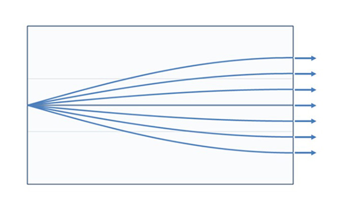
One application of the i-GRIN lens is as a four-channel collimated beam generator. The ray trajectory of a GRIN lens can be simulated by the refractive index distribution coefficient, g .
Incoming light from the optical axis center of a GRIN lens, as the point light source, becomes parallel at a pitch point of 1/4P along the GRIN lens length, which thereafter, focuses at a pitch point of 2/4P.
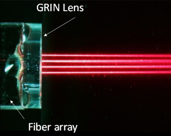
Therefore, four collimated light beams (Fig.3-5, Fig.3-6) should exit at different end surfaces of a GRIN lens when four-channel capillary-type fiber arrays and four-channel i-GRIN lenses are combined where the fiber core center and the optical axis center of the GRIN lens are aligned. Coupling of fiber arrays and i-GRIN lenses can be performed either through use of an adhesive agent or fusion splice. The capillary-type fiber array diameter and the outer diameter of the i-GRIN lens can be as small as 1.5 mm.
The example introduced here is a four-channel system, however, NOEL can also offer 8-, 12- and 16-channel components, and 2D integration (e.g., 3×3, 4×4, 8×8 and 12×12).
The light intensity distribution I (r, z) in a plane perpendicular to the traveling direction of the collimated light is generally expressed by equation (3) and is referred to as a Gaussian beam:
I(r,z)=exp(-2*r2/ω2(z)) (3)
The width, w (z), of the intensity distribution, where the light intensity at r = 0, is 1 / e2 and is referred to as the spot size of the Gaussian beam (Fig. 3-7). Additionally, the position of z at which w (z) is minimized in the light traveling direction (here, z = 0) is referred to as a beam waist position, and the spot size at this position is defined as the beam waist size, w0.
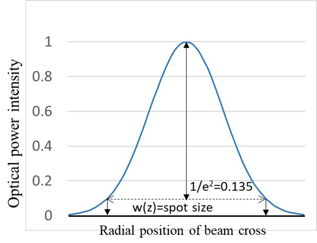
Figure 3-8 shows how such a Gaussian beam propagates. The spread angle θ of the Gaussian beam is approximately expressed by equation (4):
θ=λ/(π*ω0*n) (4)
The collimated light beam emitted from the lens is narrowed at the beam waist position, z = 0, and thereafter, spreads at an angle θ.
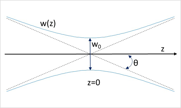
Figure 3-9 shows the results of the actual collimated beam observation.
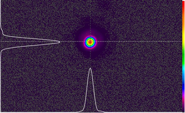
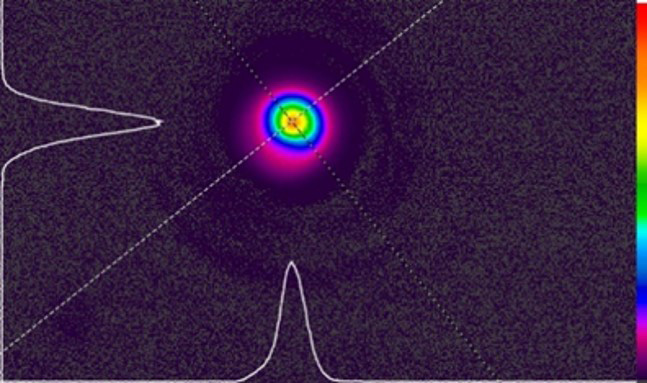
Fig.3-9 Observations of the beam profile(Ophir)
Table 3-1 and Fig. 3-10 show the beam waist position and beam waist size as a function of i-GRIN lens size.
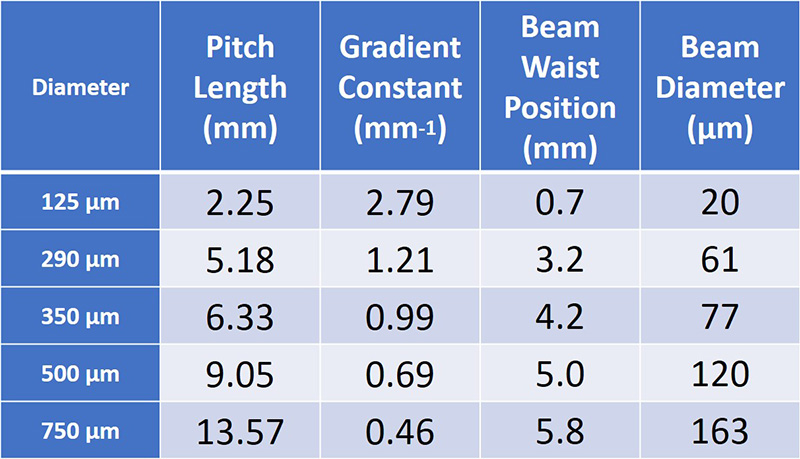
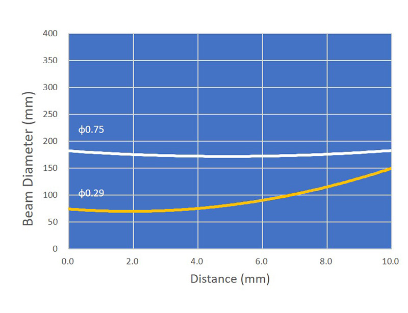
Nakahara Opto-Electronics Labs., Inc. has the ability to customize the GRIN lens diameter and the number of arrays according to the needs of the customer.
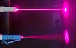
Figure.3-11 shows collimated light emitted from a multimode LC connector (a). Here, a GRIN lens is fused to the tip of the multimode optical fiber. For comparison, the light emitted from an optical fiber without a GRIN lens is also shown (b), and it can be seen that the emitted light is neatly collimated by the GRIN lens.
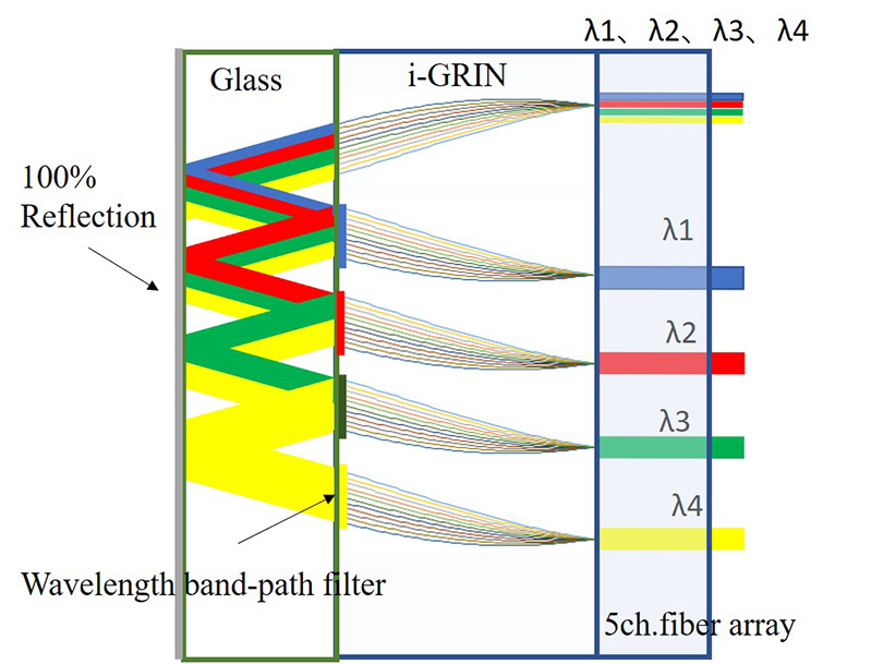
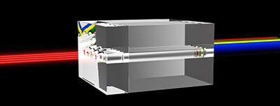
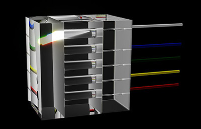
The collimated light described above can be applied to various optical components. The most typical applications for optical communications are four-wave and eight-wave coarse wavelength division multiplexing (CWDM) filters. By using a multilayer dielectric films as wavelength filters with a 4-channel i-GRIN and a 5-channel fiber array, the CWDM components, shown in Fig. 3-12, are expected to be realized. There is no need to align the lens position for each wavelength and to undertake the corresponding assembly, thus increasing productivity. Furthermore, such components will be compact and highly reliable that are resistant to temperature changes and vibrations.
By adopting the same concept, numerous components that have been assembled by aligning the lens position for each wavelength or for each signal channel hitherto, can be easily arrayed together using an i-GRIN lens. For example, the concept can be applied to mechanical transfer (MT) connectors for single mode use with a lens mounted at the front-end, array-type bi-directional couplers (BiDi) and array-type isolators.
The concept is not limited to optical communication components, and can be applied to numerous other components such as general optical sensor arrays, optical units for spectroscopic analysis, optical systems for small and portable polymerase chain reactions (PCRs), optical systems for optical coherent tomography (OCT), and a fiber scope for medical equipment. In addition to selling i-GRIN lenses, Nakahara Opto-Electronics Labs., Inc will undertake contract development and commercialization of optical components using i-GRIN lenses in response to customer requests. For further information, please contact us for details at:contact form.
3-3-2.Fiber arrays for vertical coupling of silicon photonics waveguides
Recently, silicon photonics that employ silicon waveguides are actively deployed at data centers. The silicon photonics is regarded as an essential technology for future 6G, autonomous driving, IoT, and AI. However, the technology for connecting silicon waveguides and optical fibers is still immature, which hinders the full-scale introduction of silicon photonics to the market. The light spot size of silicone waveguides is as small as 1–3 μm, and therefore, coupling silicone waveguides to normal single mode fibers having a spot size of 10 μm is difficult. To circumvent this problem, a wealth of interdependent research has focused on developing facile processes to couple the single mode fibers by forming gratings on the waveguides and ejecting light onto the upper part of the waveguides.
When a normal optical fiber array is used, the optical fibers extend to the upper part of the waveguides, resulting in a thicker component, which fails to meet the demand for thinner devices and equipment. In response, fiber arrays are, in some cases, being fabricated by bending the optical fibers. This technique, however, can have a negative impact on the reliability, which concomitantly, increases optical loss and costs as optical fibers are vulnerable to bending.
Nakahara Opto-Electronics Labs., Inc. devised a thin fiber array by bending light itself without bending the optical fiber. This technique is referred to as the straight-type low profile coupler (S-LPC). Since the optical fiber remains straight, there is essentially no breakage, no deterioration in reliability, and no loss increases due to bending of the optical fibers. The conventional V-groove type and capillary type fiber arrays can be used as is. The S-LPC parts can easily achieve a height of only ~3 mm but can be as thin as 1 mm or less.
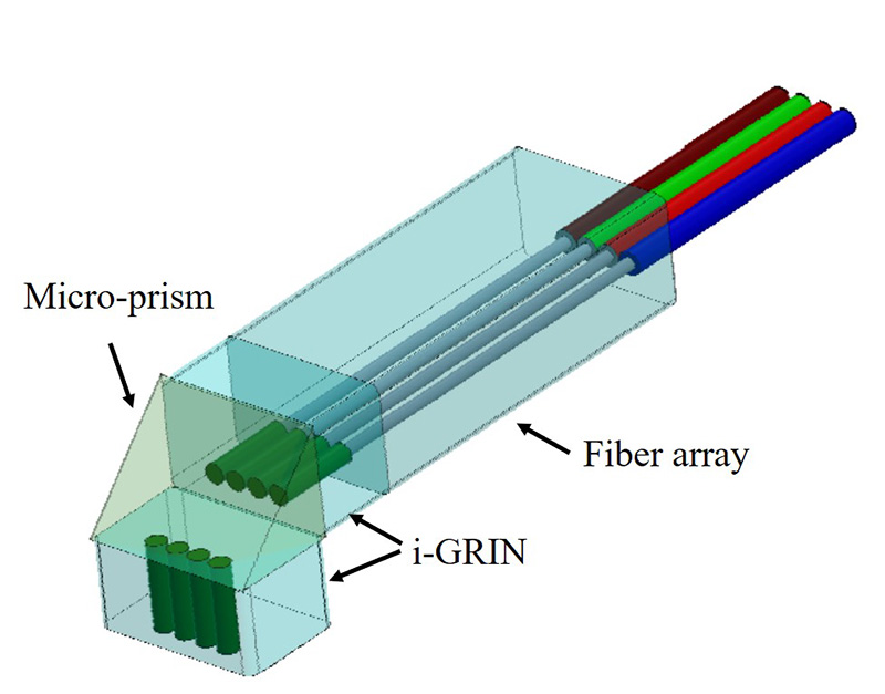
Figure 3-13 shows an example of S-LPC using two GRIN lenses. In this case, the light from the silicon chip is collimated and coupled to the optical fiber, thus allowing for easier align.
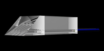
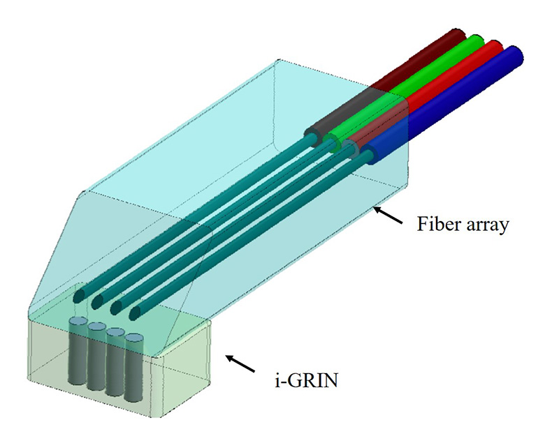
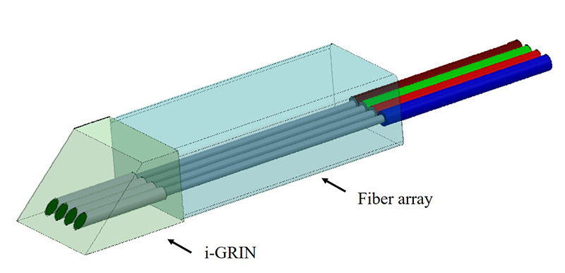
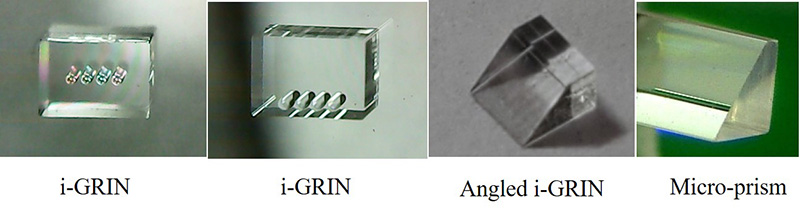
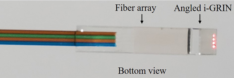
Figure 3-14 shows an example in which light from an angled fiber array is directly coupled to a silicon chip through an i-GRIN lens. Figure 3-15 shows an example in which light from angled i-GRIN is coupled to a silicon chip directly. The S-LPCs shown in Fig. 3-14 and Fig. 3-15 offer the simplest structure and ultra-thin (1mm or less) fiber coupling components for silicon photonics.
The i-GRIN lenses and micro-prism are shown in Fig.3-16, and 4 optical output from the angled i-GRIN can be observed in Fig. 3-17.
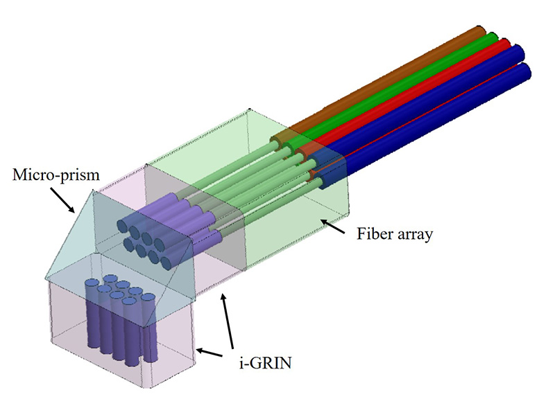
Furthermore, an i-GRIN lens can be arranged not only in one dimension but also in two dimensions, as shown in Fig. 3-18. By using a two-dimensional i-GRIN lens and a two-dimensional capillary fiber array, the two-dimensional S-LPC, shown in Fig. 3-19, can be realized.
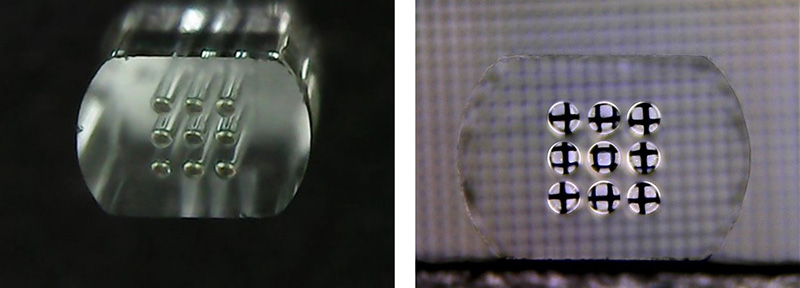
Typically, the fiber array pitch (spacing of each fiber) cannot be smaller than the outer diameter of the optical fiber, 125 µm (or 80 µm). However, by using the two-dimensional S-LPC, the fiber array pitch can be arbitrarily narrowed. Correspondingly, if the waveguide spacing of the silicon chip is also reduced, the width of the silicon chip becomes narrower and the chip area becomes smaller. In other words, a two-dimensional S-LPC will contribute to the economics of silicon chips.
For details, please feel free to contact us at: contact form
3-3-3. Application to fan-out /fan-in multi-core fibers
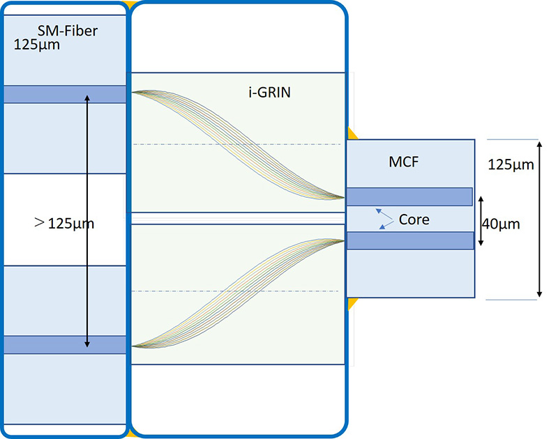
Multi-core fibers (MCFs) have attracted recent attention because they are capable of transmitting a very large amount of data in a limited space with a single fiber. Additionally, the MCF shape is round and thin, making it easier to utilize the inside and between devices when compared with ribbon fibers. However, the biggest problem to circumvent with respect to the practical use of MCFs is that, hitherto, there is no practical fan-out/fan-in component.
The use of an i-GRIN lens allows for a completely new concept of fan-out/fan-in components for MCFs. Figure 3-20 shows the ray trajectory of the MCF fan-out/fan-in component using an i-GRIN lens. A fan-out/fan-in effect can be achieved by offsetting the entering/emitting light from the optical axis of the GRIN lens. Figure 3-20 shows an example where the core spacing of the MCF component is 40 μm, which is expanded to more than 125 μm.
It can be said that if the above MCF fan-out/fan-in component is used together with the 2D S-LPC mentioned in 3-3-2, a new optical wiring device for inside and between the optical equipment will be realized.
3-3-4.Application to virtual reality (VR) glasses and retina glasses
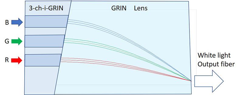
VR glasses and retina glasses require devices that combine red (R), green (G) and blue (B) light. This RGB coupler can also be realized by using i-GRIN lenses. Figure 3-21 shows the configuration and ray trajectory for this application device. First, the RGB light is converted into collimated light by an i-GRIN lens (A) and incident on the GRIN lens (B) for coupling. The incident position of each RGB light source is designed to focus on the same exit end face of the coupling GRIN lens (B), taking into account the wavelength dependence of the refractive index. The RGB coupler of the i-GRIN lens is expected to possess excellent features such as easy coupling and alignment of the light source and lens, and in being small and light weight with low losses. Furthermore, this RGB coupler demonstrates strong vibration properties and is highly reliable.
3-3-5.Application to Components for Decarbonization
In recent years, power consumption in data centers has exploded. This is not only due to the increasing amount of information from the spread of smartphones, automated driving, IoT, etc., but also to the recent rise of AI, which has led to the enormous energy consumption of AI chips. By 2030, data centers will use 9% of the world’s total electricity generation, and by 2050 this will reach 32%.
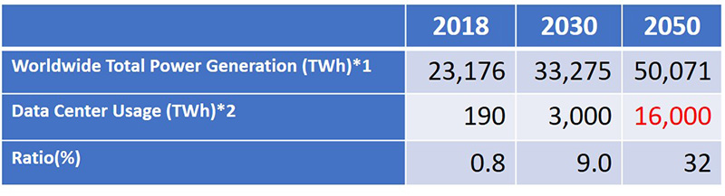
The combined annual power generation of Units 1 to 6 of the Fukushima Daiichi Nuclear Power Plant is 41 TWh (100% operating rate), and those of Units 1 and 2 of the Three Mile Island Nuclear Power Plant in the United States is 15.7 TWh (100% operating rate), which is far from the power consumption of data centers after 2030.
Table 3-3 shows the power usage ratio of various devices inside a data center. Optical transmission equipment uses only 5% of the total power, so even if energy conservation efforts are made using silicon photonics, the effect will be minimal. Table 3-3 shows that the most effective way to reduce power consumption is to reduce the power used for air conditioning (cooling).
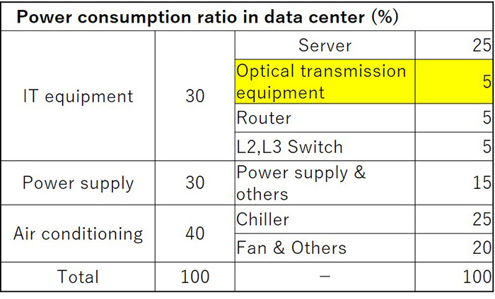
Ref. Calculated based on “2021 Data Center & Key Device Related Market Research,” Fuji Chimera Research Institute 2021.
For this reason, attempts have been made to install data centers in the Arctic or on the ocean floor, but these were not practical and unsuccessful. Currently, technology that uses water cooling or liquid immersion to cool various devices such as servers and switches rather than air conditioning is attracting attention. The liquid immersion method in particular is calculated to be effective in reducing the electricity required for equipment cooling by 94% compared to air conditioning, and is the technology most expected to contribute to decarbonization.
However, the immersion method has serious problems that must be solved. In the immersion method, servers, switches, and optical transmission devices are all immersed in a coolant such as oil. It has been confirmed that electronic devices and semiconductors maintain their insulation even when immersed in oil, and there are no problems. However, optical components and optical connectors that use lenses and prisms will experience significant changes in optical performance due to the refractive index of the coolant. Optical transceivers will no longer work. In addition, once an optical connector is detached, it will no longer be possible to connect to a PC (PC connection: physical contact), which will have a negative effect on connection loss and reflection characteristics and may cause equipment failure.
Integrated GRIN lenses are a powerful component that can solve these problems.
A normal spherical lens refracts light at the boundary between the air and the curved lens, forming a parallel beam as shown in Fig. 3-22. However, in liquids, the refraction angle changes depending on the refractive index of the liquid, so the light does not become a parallel beam. On the other hand, in a GRIN lens, the refractive index distribution inside the glass plays the role of the sphere of a normal lens, so the light rays trace the same trajectory and form a parallel beam, regardless of the external environment, whether in air or liquid. This phenomenon has been known for a long time (*). Nakahara Optoelectronics Laboratory Co., Ltd. is developing this to apply to optical transceivers and optical connectors, making it possible to use optical transmission equipment directly in liquid immersion.
*:USP5738676 ”Laser surgical probe for use in intraocular surgery” Apr.14, 1998
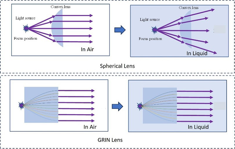
Figure 3-23 shows various types of optical transceivers that can be used for liquid immersion.
Most pluggable optical transceivers present used (Fig. 3-23-(a)) change their lens action when immersed in liquid as is, and they cannot be operated as optical transceivers. For this reason, AOCs (Active Optical Cables), in which the outer front surface of the transceiver is molded in resin, are used as optical transceivers for liquid immersion (Fig. 3-23-(b)). AOCs can be used for immersion cooling in data center servers and switches, but there is still a major issue that needs to be resolved. This is because the entire transceiver is resin molded, so the optical connector and optical transceiver cannot be separated.
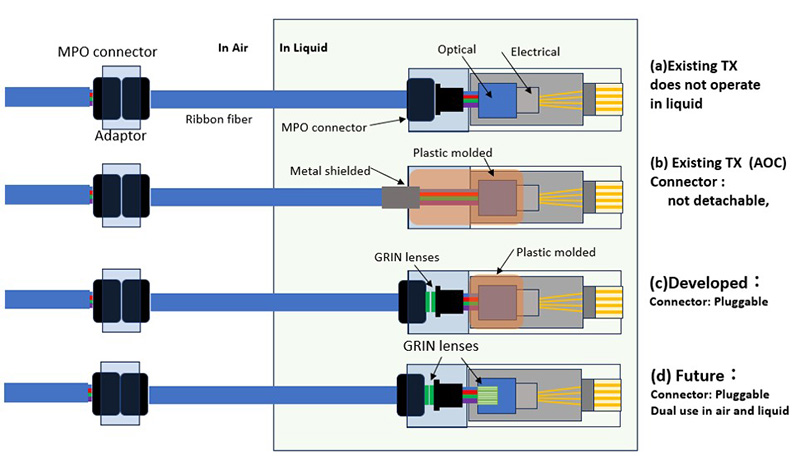
This leads that optical transceivers must be replaced with the optical cable still attached during maintenance. In particular, when dozens or hundreds of optical cables are bundled and attached to servers and switches, the time and cost of maintenance can be enormous. This is also a barrier to the widespread adoption of immersion cooling systems, and is an issue that needs to be urgently addressed in order to decarbonize.
Figure 3-23-(c) shows an MPO optical connector with a GRIN lens attached to its end face and molded resin to prevent the intrusion of immersion media into the optical part inside the optical transceiver. The MPO has a GRIN lens to expand the beam to prevent deterioration of the characteristics due to liquid contamination, dust, etc., and changes in the refractive index when the connector is inserted or removed.
KDDI Corporation is developing immersion cooling systems for commercialization, and has achieved a 94% reduction in server cooling power by 2023, with a PUE = 1.02 (PUE: Power Usage Efficiency, the amount of power used by the entire data center divided by the amount of power used only by IT equipment. PUE = 1.0 is the ideal value, but it can be as high as 1.9 for air conditioning.
Nakahara Optoelectronics Laboratory Co., Ltd. prototyped the transceiver shown in (c) and conducted verification experiments using an actual immersion system in collaboration with KDDI Corporation at the KDDI Corporation Oyama Network Center from February to May 2024 (Fig 3-24).
In the KDDI Corporation immersion equipment, it was confirmed that ARISTA, DELL, HP, and CISCO servers and switches could be connected and linked with an optical transceiver (multimode 100 Gbps, 12-core MPO connector interface). It was then confirmed that there was no change in the transmission characteristics even if the optical connector detached and then reconnect it in the liquid.

(at KDDI Oyama network center immersion cooling system)
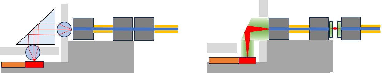
Present: Conventional TX/Rx Future: Dual use in air and liquid
Fig.3-24-2
In the future, Nakahara Optoelectronics Laboratory Co., Ltd. will cooperate with optical transceiver manufacturers to apply integrated GRIN lenses to the interface between the optical components inside the optical transceiver and the optical fiber (Fig.3-24-2), aiming to realize a pluggable optical transceiver that can be used in both air and liquid. This technology is expected to contribute to the construction of all-photonic networks that make extensive use of silicon photonics and CPO (Co-Package Optics).